
The 555 timer is one of the most popular and versatile integrated circuits (ICs) used in electronics. Designed in the early 1970s, this compact chip is widely used in timing, pulse generation, and oscillator applications. Whether you’re building a simple LED flasher or a more advanced timing system, the 555 IC offers a robust and beginner-friendly solution.
Table of Contents
What Is a 555 Timer and How Does It Work?
The 555 timer IC is a precision timing device capable of generating accurate time delays or oscillations. It can operate in three primary modes:
- Monostable (one-shot pulse)
- Astable (oscillator)
- Bistable (flip-flop)
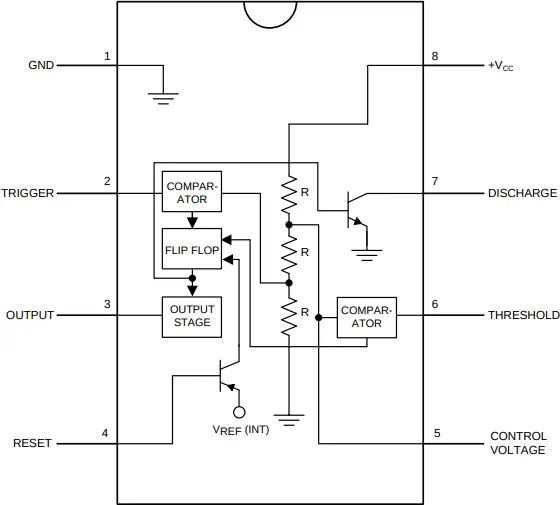
Internally, the 555 chip contains two voltage comparators, a flip-flop, a discharge transistor, and a voltage divider. These elements work together to provide consistent timing behavior based on resistor-capacitor (RC) networks connected externally.
The following image shows the internal parts of a 555 IC. In addition it shows the pinout of this integrated circuit.
Common 555 Timer Circuits
Below are some basic yet essential 555 circuits you can build:
1. 555 IC Monostable Circuit
- Produces a single output pulse when triggered.
- Ideal for applications like timers or switches.
See the monostable 555 IC circuit example in the 555 timer circuits article.
2. 555 as Astable Multivibrator
- Oscillates between high and low states continuously.
- Used in applications such as blinking LEDs and clock signals.
See the astable multivibrator 555 IC example circuit.
3. NE555 Circuit as Bistable Latch / Flip-flop
- Functions as a flip-flop (on/off toggle).
- Useful for switching applications.
See the bistable 555 IC example circuit for more details.
Understanding the 555 IC Diagram and Pinout
Here is a simplified 555 IC diagram and table with standard DIP-8 pinout:

| Pin Number | Name | Function |
|---|---|---|
| 1 | GND | Ground |
| 2 | Trigger | Activates timing interval |
| 3 | Output | Output signal |
| 4 | Reset | Resets the timing cycle |
| 5 | Control | Controls threshold (optional) |
| 6 | Threshold | Ends timing when reached |
| 7 | Discharge | Discharges capacitor |
| 8 | VCC | Supply voltage (4.5V to 15V) |
This 555 chip schematic layout helps in properly wiring up your circuit for desired behavior.
Tips for Using the 555 Timer
- Use a decoupling capacitor (0.01 µF to 0.1 µF) between VCC and GND to minimize noise.
- Choose quality resistors and capacitors for stable timing intervals.
- In 555 oscillator circuits, ensure capacitors are rated well above the supply voltage.
- Use simulation software to test your 555 circuit before building on a breadboard.
- When using the NE555 variant, confirm operating voltage range and package compatibility.
Did You Know About the 555 Timer?
- The 555 timer was invented by Hans R. Camenzind in 1972 while working for Signetics.
- Over one billion units of the 555 chip have been sold worldwide, making it one of the most produced ICs in history.
- The NE555 is the most widely used version, designed to work at 4.5V to 15V with excellent stability.
- The original name “555” comes from the three 5kΩ resistors used in the voltage divider network inside the IC.
Frequently Asked Questions About the 555 Timer
What is the NE555?
The NE555 is a commonly used version of the 555 timer IC manufactured by Texas Instruments and others. It features high temperature stability and supports operation from 4.5V to 15V.
Can the 555 timer generate a square wave?
Yes, in astable mode, the 555 functions as an oscillator that outputs a square wave signal.
What is the difference between monostable and astable 555 circuits?
A monostable circuit produces one output pulse per trigger, while an astable multivibrator continuously toggles between high and low states, generating a waveform.
Is the 555 timer still used in modern electronics?
Absolutely. Despite being over 50 years old, the 555 timer remains widely used due to its simplicity, low cost, and versatility in timing applications.
How can I calculate the timing interval in a 555 timer circuit?
Use the following formulas:
- Monostable Mode:
Time (T) = 1.1 × R × C - Astable Mode:
T = 0.693 × (R1 + 2R2) × CFrequency = 1.44 / ((R1 + 2R2) × C)
Can I replace the 555 timer with a microcontroller?
While microcontrollers offer more flexibility, the 555 timer IC is ideal for simple, cost-effective solutions without programming.
Conclusion
The 555 timer remains a foundational component in electronics, offering reliable timing and oscillation capabilities in a wide range of circuits. Whether you’re experimenting with an NE555 circuit or designing a 555 as astable multivibrator, understanding how this chip works is key for any beginner or hobbyist. Its simplicity, availability, and functionality make the 555 timer a must-know component in your electronics journey.