
555 timer circuits are a foundational set of designs used to create timers, pulse generators, and simple oscillators. This article explains how 555 timer circuits work, compares common chips such as the NE555 and NE555P, and shows practical examples, using the 555 timer IC and LM555 timer circuit variants, so you can build reliable projects quickly.
Table of Contents
- What are 555 Timer Circuits?
- How the 555 Timer IC Works
- Common 555 Timer Circuits: Astable, Monostable and Bistable
- Design Example: a 555 Timer Circuits Astable LED Flasher
- Using Parts and Documentation
- 555 as Astable Multivibrator
- Tips for 555 Timer Circuits
- Did You Know About 555 Timer Circuits?
- Frequently Asked Questions About 555 Timer Circuits
- Conclusion
What are 555 Timer Circuits?
555 timer circuits use a stable, well-documented timer IC to generate time delays or oscillations. The original 555 design is packaged as a small DIP or SOIC device and appears in variants labeled NE555, LM555, and NE555P timer circuit types. Typical 555 timer circuits fall into two broad groups: timing (monostable) and oscillation (astable).
A short list of what 555 timer circuits can do:
- Produce single pulses of precise duration (monostable mode).
- Generate continuous square-wave clocks for LEDs, buzzers, or microcontrollers (astable mode).
- Debounce switches, produce PWM, or function as a simple 555 chip oscillator.
How the 555 Timer IC Works
At its core the 555 timer IC contains comparators, a flip-flop, a discharge transistor, and an output driver. The comparators look at a voltage divider (1/3 VCC and 2/3 VCC) and change the flip-flop state according to trigger and threshold inputs. The discharge transistor lets a timing capacitor charge and discharge through resistors to set intervals used in 555 circuit timing.

Key pins to remember for 555 timer circuits:
| Pin | Name | Function |
|---|---|---|
| 1 | GND | Ground (connects to 0V of power supply) |
| 2 | TRIGGER | Active-low trigger input (starts timing in monostable) |
| 3 | OUTPUT | Output (drives load) |
| 4 | RESET | Active-low reset |
| 5 | CONTROL | Control voltage |
| 6 | THRESHOLD | Threshold (ends timing) |
| 7 | DISCHARGE | Discharge transistor for timing capacitor |
| 8 | VCC | Power supply (typically 5–15 V) |
Consult the 555 timer datasheet for absolute maximum ratings, recommended operating conditions, and typical voltage levels for reliable 555 timer circuits. Be sure to select the datasheet for the specific 555 IC variant that you are using.
Common 555 Timer Circuits: Astable, Monostable and Bistable
There are three common modes used in most 555 circuit applications:
- Astable (oscillator): The 555 as astable multivibrator produces a continuous square wave. Frequency and duty cycle are set by two resistors and a capacitor. This is the classic 555 chip oscillator use.
- Monostable (one-shot): A single pulse is generated when the trigger pin is pulled low. Pulse width depends on R×C.
- Bistable (flip-flop): The 555 acts as a basic latch with set and reset inputs.
Use cases for these 555 timer circuits include LED blinkers, tone generators, PWM control for motors, and simple alarm circuits. Practical examples of all three circuits follow. These are easy circuits to build and test as they all demonstrate the 555 timer modes using an LED as an output.
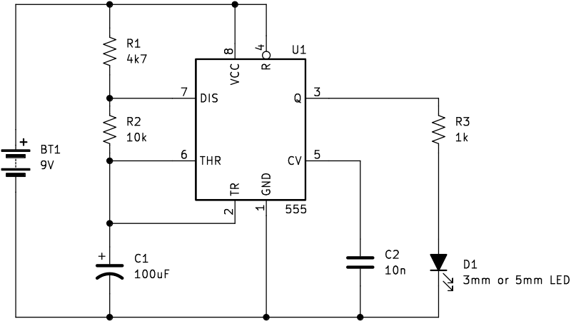
Astable 555 Timer LED Blink Circuit Example
The following circuit is a basic LED blink circuit that flashes an LED on and off using a 555 timer IC. It is easy to build on an electronic breadboard.
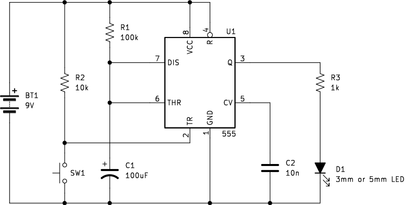
Monostable 555 Timer Circuit Example
Press switch SW1 in the following monostable 555 timer IC circuit. This starts the timing period that leaves LED D1 on for the period set by R1 and C1.
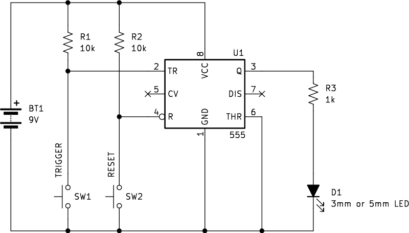
Bistable 555 Timer Circuit Example
The following bistable circuit keeps the LED in a set or reset state, even after releasing the switch. The 555 effectively ‘remembers’ the state that it was put in.
Design Example: a 555 Timer Circuits Astable LED Flasher
The same astable LED flasher circuit from above can be built using different component values as described below. This example describes a standard astable 555 timer circuit that flashes an LED.
Component list:
- 1 × 555 timer IC (NE555 or LM555)
- R1 = 1 kΩ, R2 = 10 kΩ, C1 = 10 µF
- LED + series resistor (330 Ω)
- C2 is optional and provides some voltage smoothing
- 5–12 V supply
Basic operation:
- Resistors R1 and R2 and capacitor C1 set charge/discharge times.
- The output toggles between HIGH and LOW, turning the LED on and off.
- Frequency ≈ 1.44 / ((R1 + 2·R2)·C1).
This simple 555 circuit is an ideal first project for learning how component values affect frequency and duty cycle.
Using Parts and Documentation
When sourcing parts, note differences:
- NE555 is a common manufacturer part number; NE555P timer circuit usually refers to a circuit that uses the DIP package.
- LM555 timer circuit components follow the same pinout but may differ slightly in timing characteristics and temperature range.
- Always consult the specific 555 timer datasheet for the exact IC you have: confirm supply voltage range, output current limits, timing capacitor ESR recommendations, and thermal limits.
Working with correct datasheet values prevents overheating and unreliable timing in your 555 timer circuits.
555 as Astable Multivibrator
The 555 as astable multivibrator is widely used as a clock source or tone generator. You can create:
- Square-wave audio tone generators (simple beepers). Set the 555 circuit to output a higher frequency than the low frequency LED blink example.
- Test clocks for counters or microcontrollers.
- PWM-style control when combined with a variable resistor.
For audio, the 555 chip oscillator can drive a small speaker through a coupling capacitor; limit current and avoid driving large loads directly from the 555 output.
Tips for 555 Timer Circuits
- Use bypass capacitors (0.01 µF) between VCC and GND close to the IC to prevent false triggering.
- Add a small resistor (≈10 Ω) in series with the discharge pin for very low R values to protect the IC.
- If you need precise timing, use higher-quality capacitors (low leakage, low tolerance) and verify values against the 555 timer datasheet.
- For battery-powered projects choose the CMOS variants with low quiescent current when available.
- Avoid long wires on timing capacitors — keep layout compact to reduce stray capacitance and noise.
Did You Know About 555 Timer Circuits?
- The 555 timer was introduced in 1972 and remains one of the most produced ICs in history.
- Engineers and hobbyists still prefer the 555 chip oscillator for simple timing tasks because it requires minimal external parts.
- You can cascade 555 timer circuits to create more complex pulse sequences or convert pulses to analog waveforms using RC networks.
Frequently Asked Questions About 555 Timer Circuits
What is the difference between NE555 and LM555?
Both are implementations of the same 555 timer design; differences are minor, manufacturer, packaging, and sometimes operating temperature or current specifications. Check the 555 timer datasheet for specifics.
How do I calculate the frequency of a 555 timer circuit in astable mode?
Use the formula f ≈ 1.44 / ((R1 + 2·R2)·C). Adjust R1, R2, or C to achieve the desired frequency.
Can I use a 555 timer IC to drive motors?
The 555 output can source/sink limited current. For motors use a driver transistor or MOSFET and isolate the IC from motor load and back-EMF.
Where can I find a reliable 555 timer datasheet?
Manufacturer websites (e.g., Texas Instruments, ON Semiconductor) host authoritative 555 timer datasheet PDFs. Always consult the datasheet for the specific part number you buy.
Is the 555 suitable for precision timing?
For high precision use crystal or microcontroller timers. The 555 is best for approximate timing and simple oscillators.
Conclusion
555 timer circuits are versatile, inexpensive, and perfect for learning timing and oscillator concepts. Whether you choose an NE555, LM555 timer circuit, or NE555P timer circuit, the fundamentals remain the same: use the datasheet, pick stable components, and test your 555 timer circuits on a breadboard first. With a few resistor and capacitor changes you can design monostable pulses, astable oscillators, and practical 555 chip oscillator projects that get you building fast.